How Substrates, Fasteners and Pull-Out Testing Shape Rainscreen Attachment
 Code Compliance
Rainscreen attachment should be developed around the actual supporting substrate and project loads. Those conditions influence bracket layout, primary fastener selection, and whether field verification such as pull-out testing is appropriate. Within broader aluminum cladding code compliance, the attachment strategy completes the load path from the facade system into the supporting construction.
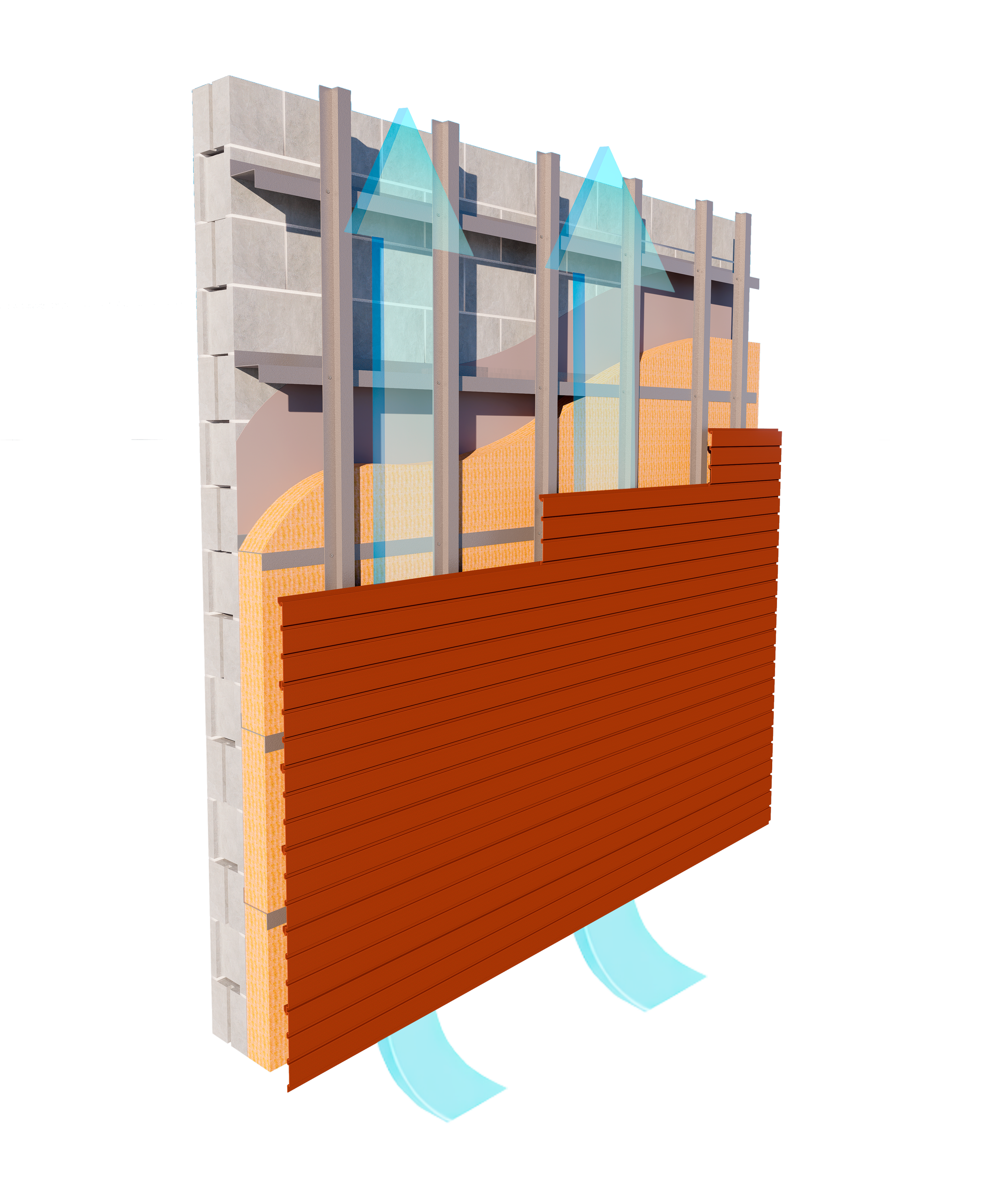
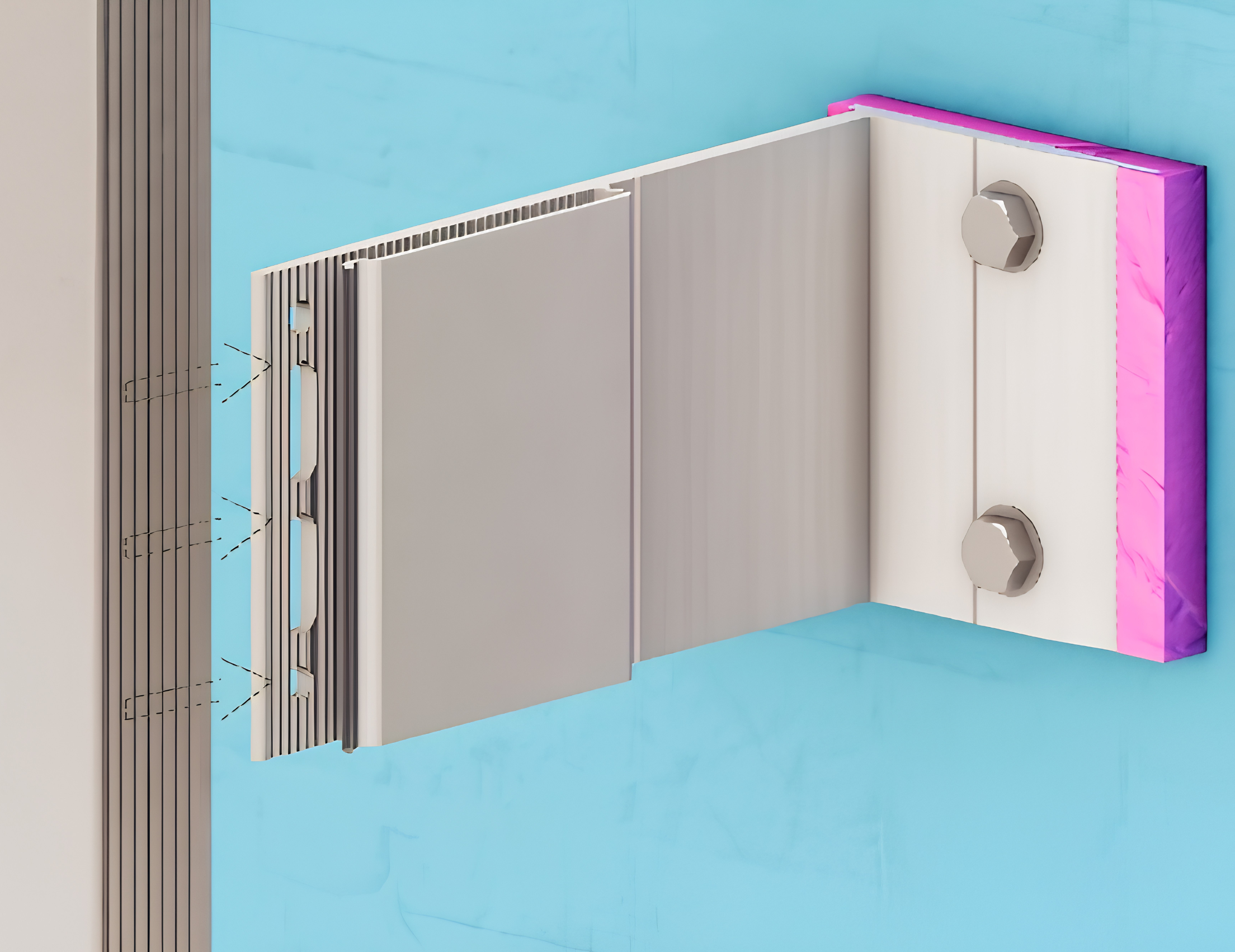
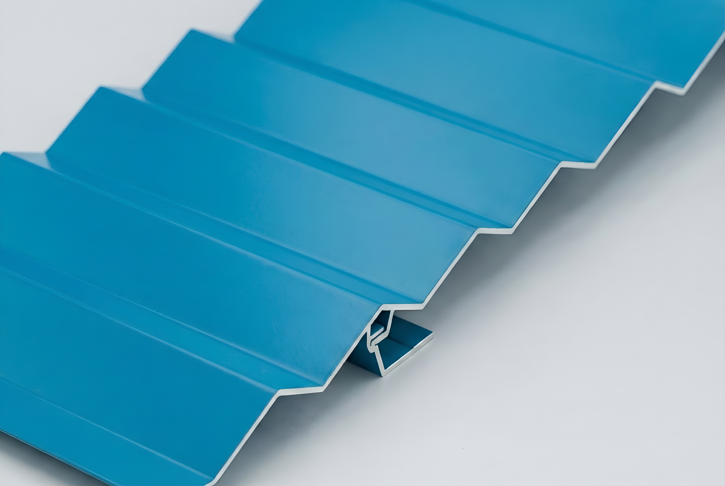
With aFrame thermally broken subframing, aPlank provides an adjustable attachment plane while primary fasteners remain dependent on wall type and structural requirements. The objective is to align those conditions before attachment details are released.
Start with the Substrate, Not the Fastener
A fastener cannot be selected meaningfully without defining what it attaches to. Concrete, CMU, brick masonry, and framed walls introduce different questions about embedment, engagement, substrate condition, and connection location. The wall description on a detail may therefore be only the starting point.
| Supporting condition | Attachment consideration |
|---|---|
| Concrete | Anchor type, embedment, edge conditions, and verified capacity |
| CMU / block | Hollow or grouted condition, anchor location, and substrate variability |
| Brick / masonry | Material condition and whether project-specific field verification is required |
| Framed wall | Framing material and thickness, fastener engagement, and attachment location |
For aFrame, aPlank recommends primary fasteners based on wall type and recommends pull-out testing for attachment into blockwork and brick.

Adapt the Attachment Plane to the Project
Explore aFrame thermally broken subframing for a rainscreen attachment plane configured around project wall conditions.
Explore aFrame →Follow the Load Path Through the Attachment System
Project wind-performance requirements establish part of the demand the facade must resist. That demand still has to move through the attachment system into the supporting construction. The 2024 IBC ties exterior wall-covering attachment to applicable structural wind loads.
Cladding and rail
Panel reactions enter the supporting profile or rail at defined attachment points.
Bracket and layout
Bracket spacing and tributary area influence the demand carried by each connection.
Primary anchor and substrate
The primary anchor transfers dynamic and dead loads from the subframe into the supporting wall.
For aFrame, the primary anchor type and size are determined by the dynamic and dead loads they must resist. The final connection remains project-specific.

Bracket spacing and attachment layout determine how project loads are distributed to the supporting construction.
“Anchor capacity only becomes meaningful when it corresponds to the substrate and attachment conditions used on the project.”
aPlank Technical Engineering TeamWhen Pull-Out Testing Is Appropriate and What It Verifies
aPlank recommends pull-out testing for attachment into blockwork and brick, but does not prescribe a specific ASTM test method. ASTM E3121/E3121M provides procedures for field tensile and shear testing of anchors in concrete and masonry, including ultimate-load testing and proof-load testing used to verify proper installation.
The distinction matters. ASTM states that confined proof-load tests used to verify installation are not used to develop design values. For concrete anchor qualification and design data, ASTM E488/E488M addresses laboratory strength testing. Field results should therefore be interpreted according to the test purpose, not treated automatically as connection design capacity.
Define the Attachment Conditions Before Release
Before release, the attachment package should define the supporting substrate, design pressures, cladding dead load, bracket and rail layout, primary anchor, and any required field verification.
For aFrame, approved shop drawings establish bracket positions and fastener locations. Installation checks include primary-anchor torque settings, profile alignment, and fastener quantity and position. These checks keep installation aligned with the project-specific layout.
Resolve the Load Path Around the Actual Wall
A rainscreen attachment strategy is complete when project loads, bracket layout, primary fasteners, and the actual supporting substrate are evaluated as one continuous load path. Pull-out testing adds field verification when its purpose and acceptance criteria are clearly defined. aPlank positions aFrame within that process as an adjustable, thermally broken subframing system that can be configured around project wall conditions while preserving the need for project-specific attachment engineering.
Rainscreen Attachment: Common Questions
Does a rainscreen use the same fasteners for every substrate?
No. Primary attachment depends on the supporting construction, project loads, anchor capacity, and approved attachment design. Concrete, CMU, masonry, and framed walls are not interchangeable substrates.
When is pull-out testing appropriate for rainscreen attachment?
Pull-out testing may be appropriate when an anchor and substrate condition require field verification. aPlank recommends pull-out testing for attachment into blockwork and brick, but does not prescribe a specific ASTM test method. The project engineer or specifying authority should define the test purpose and acceptance criteria.
Can field pull-out testing establish an anchor's design capacity?
Not automatically. ASTM E3121/E3121M distinguishes between tests used to determine ultimate load and proof-load tests used to verify installation. Confined proof-load tests used for installation verification are not intended to develop design values.