Facade R-Values and U-Factors: What Aluminum Subframing Changes
 Energy Efficiency & Sustainability
An exterior wall may begin with an insulation target, but its thermal design quickly becomes an assembly exercise. Insulation thickness, bracket geometry, attachment frequency, rail configuration and facade interfaces all become part of the thermal performance represented in the project’s energy calculations.
For rainscreen assemblies, the subframing strategy is especially relevant. The support system carries the exterior cladding across the insulation layer while coordinating with insulation thickness, wall depth and structural requirements as project teams work toward the required whole-wall performance.
Understanding the relationship between R-value, U-factor and subframing connects thermal targets with a facade assembly that can be detailed and built consistently. Within aPlank facade systems, that coordination supports the broader approach to energy-efficient aluminum facade systems and complements the role of thermally broken facade subframing in reducing conductive heat transfer.
Facade R-Values and U-Factors: From Component to Assembly
R-value expresses resistance to heat flow and is commonly associated with individual insulation products or insulation layers. U-factor describes heat transmission through an assembly, with lower values indicating less heat transfer.
U-Factor
- Represents the assembled wall condition
- Can incorporate framing and attachment effects
- Supports whole-wall thermal evaluation
R-Value
- Expresses resistance to heat flow
- Commonly used for insulation layers
- Supports material-level specification
For commercial envelope compliance, the 2021 International Energy Conservation Code commercial envelope provisions include both an insulation-component R-value method and an assembly U-factor method. ASHRAE’s building-envelope guidance similarly distinguishes between material and system resistance and whole-wall thermal transmittance, including the effect of thermal bridges in whole-wall evaluation.
This distinction becomes especially useful where rainscreen attachments cross the exterior insulation. For aPlank assemblies, evaluating insulation together with the attachment configuration provides a clearer basis for coordinating aFrame geometry with the project’s thermal assumptions.

Build Around Your Thermal Goals
aFrame can support your project’s thermal and facade requirements.
Connect with our team →How Aluminum Subframing Shapes Whole-Wall Thermal Performance
Aluminum combines a high strength-to-weight ratio, durability and precise profile geometry for facade subframing. Its conductivity also makes support-system configuration an important input when the attachment plane crosses exterior insulation.
Bracket geometry and thermal breaks
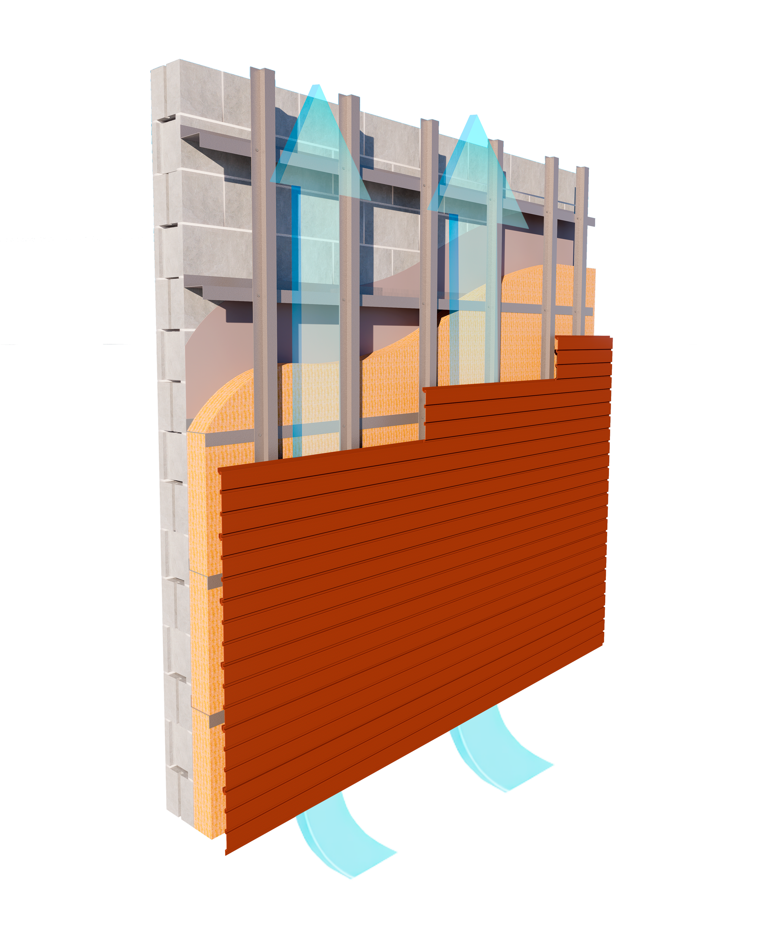
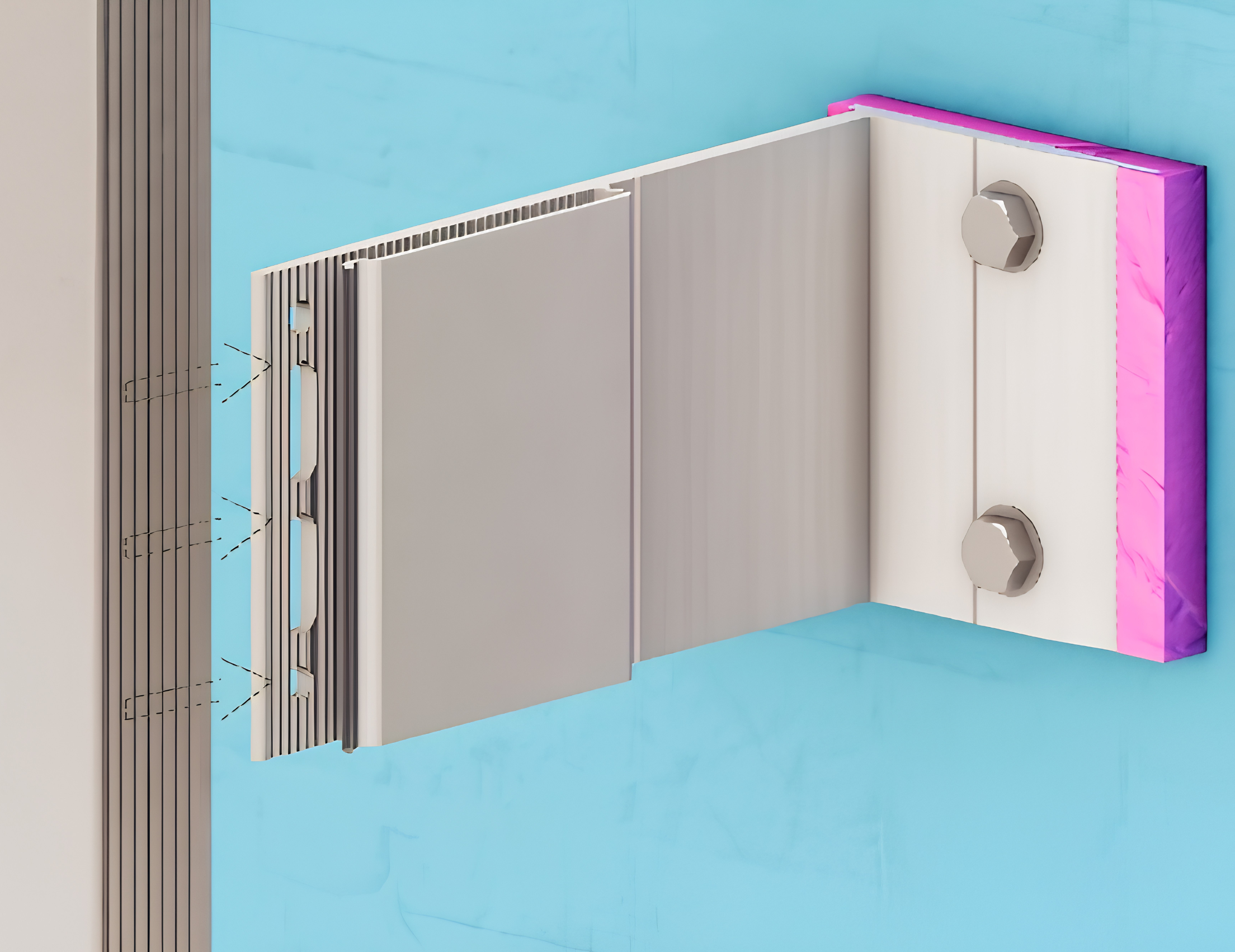
Rainscreen brackets connect the exterior support rails back to the structure, creating a direct interface between the cladding support system and the insulation layer. Their geometry, material path and thermal-break configuration influence heat transfer through those attachment points.
This is where a thermally broken attachment strategy becomes particularly valuable. aPlank’s aFrame system incorporates a thermal break within its adjustable aluminum bracket configuration, allowing the rainscreen support system to maintain the structural connection required by the cladding while reducing conductive heat transfer through the attachment plane.
This same relationship is reflected in the BC Hydro Building Envelope Thermal Bridging Guide, which evaluates brackets, clips, ties and fasteners penetrating exterior insulation as thermal-bridging conditions and includes thermally isolated attachment systems within its catalogue of wall assemblies.
Attachment frequency
Bracket spacing is also part of the thermal condition. More attachment points per unit area create a different repeating path through the insulation than fewer connections. Spacing must still satisfy wind pressures, cladding weight, substrate conditions and project engineering.
Rail configuration
Primary and secondary rails establish the attachment plane for the cladding and can influence both wall depth and continuity of the support system.
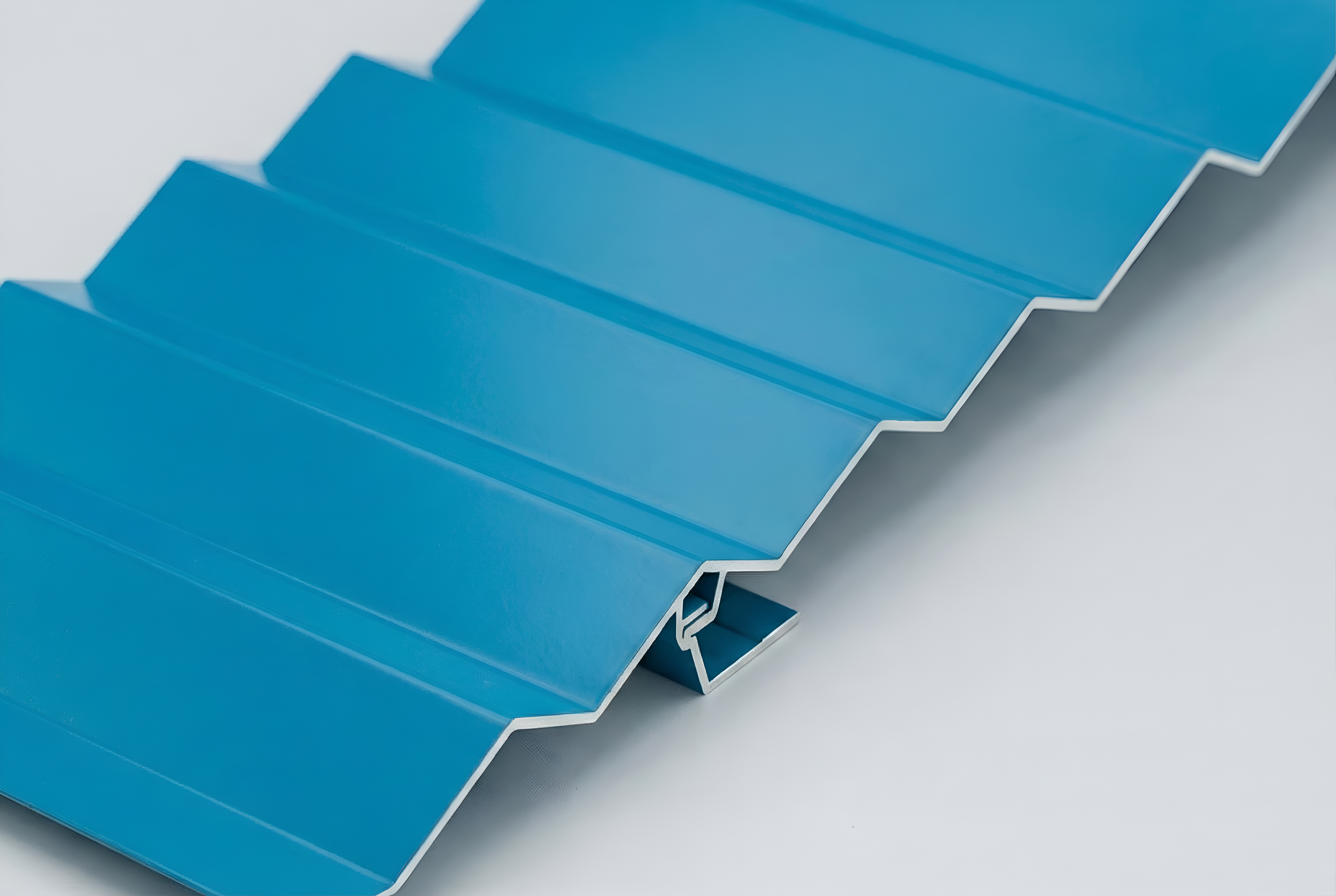
For example, aPlank’s aFrame thermally broken adjustable subframing system uses brackets with primary rail options and can accommodate different system depths. V4, V6, V8 and V10 bracket configurations provide adjustment ranges for different facade build-ups, allowing insulation depth, substrate conditions and cladding alignment to be coordinated within the support system. aFrame documentation also calls for insulation to be tightly fitted around the brackets while maintaining the ventilated cavity.

aFrame V4, V6, V8 and V10 bracket configurations provide adjustable system depths for different facade build-ups.
Extending Thermal Performance Across Facade Transitions
The repeated wall condition establishes an important baseline, while transitions connect that condition to the rest of the enclosure.
Window perimeters, slab edges, parapets, corners and roof-to-wall transitions introduce different geometries and material paths from the typical field condition. The BC Hydro thermal-bridging methodology distinguishes these interface details from clear-field assemblies and evaluates their additional heat flow separately.
Rail terminations, bracket placement and insulation interfaces may adapt locally while preserving the architectural attachment plane. Coordinating envelope design and panel, glass and facade transitions allows the thermal strategy established for the typical wall to inform openings, corners and terminations.
“The attachment strategy is part of the facade’s thermal design.”
— Facade thermal coordination principleAligning Facade U-Factors With the Specified Assembly
A useful thermal model depends on defined assembly inputs that remain coordinated with architectural details, structural engineering and facade submittals.
| Project input | Why it matters thermally | What to coordinate |
|---|---|---|
| Insulation | Establishes material resistance through the wall field. | Type, thickness and continuity around attachments |
| Brackets | Create repeating conductive paths through exterior insulation. | Geometry, thermal break and spacing |
| Rails | Establish the cladding support plane and system depth. | Primary and secondary arrangement |
| Transitions | Introduce local geometries beyond the typical wall condition. | Openings, corners, parapets and terminations |
Keeping these parameters aligned between thermal analysis and the facade package helps preserve the intended performance strategy. Product-specific information also gives project teams a defined bracket and rail arrangement to evaluate.
Specifying Subframing Around the Project’s Thermal Targets
For project teams evaluating aluminum rainscreen assemblies, subframing selection becomes part of the broader envelope-performance strategy. Relevant information includes the proposed bracket and rail configuration, thermal-break construction, attachment spacing, system depth and insulation interface.
Those parameters can then be coordinated with structural loading, cladding geometry and the thermal assumptions used for the wall. aFrame system documentation is available through the aPlank technical downloads for reviewing the attachment configuration alongside project-specific thermal analysis.
Facade R-Values, U-Factors and Subframing
How does aluminum subframing affect a facade U-factor?
Aluminum brackets, rails and fasteners create conductive paths through exterior insulation. Their geometry, thermal-break configuration and attachment density therefore contribute to the thermal transmittance of the assembled wall.
Does a thermally broken subframe eliminate thermal bridging?
A thermally broken subframe reduces conductive heat transfer through facade attachments, but project thermal performance still depends on the complete wall assembly and interface conditions such as windows, slab edges, parapets and corners.
Why should bracket spacing be included in facade thermal analysis?
Attachment frequency changes the number of repeating conductive paths through the insulation layer. Thermal analysis should therefore reflect the bracket layout being coordinated for the project rather than an unrelated generic condition.
What facade information needs to be coordinated with the energy model?
Teams should make sure the facade submittals match the assumptions used in the energy model. This includes insulation type and thickness, bracket geometry and spacing, thermal-break configuration, rail arrangement, substrate requirements, and other conditions that affect thermal performance.