Energy Efficiency & Sustainability
Energy performance is rarely determined by a single cladding material. It is established by how the exterior wall manages heat flow, air leakage, moisture, solar exposure, and the many structural connections that pass through the insulation layer. For commercial facade teams, the relevant question is therefore not whether aluminum is inherently “energy efficient,” but whether the complete aluminum facade assembly supports the project’s modeled performance. aPlank extruded aluminum facade panels and the aFrame thermally broken subframing system are best evaluated within that complete assembly.
As energy codes and high-performance building targets place greater emphasis on whole-wall behavior, facade specifications must account for insulation continuity, attachment geometry, thermal bridges, and material documentation together. As a manufacturer, aPlank supports that process by providing aluminum cladding systems, subframing options, technical information, and project-specific product guidance that design teams can evaluate against the assembly’s performance requirements.
Evaluate the Assembly, Not Only the Cladding
Metal cladding sits outside the primary thermal control layer in most rainscreen wall assemblies. Its contribution is tied to how effectively the system protects that control layer, accommodates continuous exterior insulation and limits conductive paths through the wall.
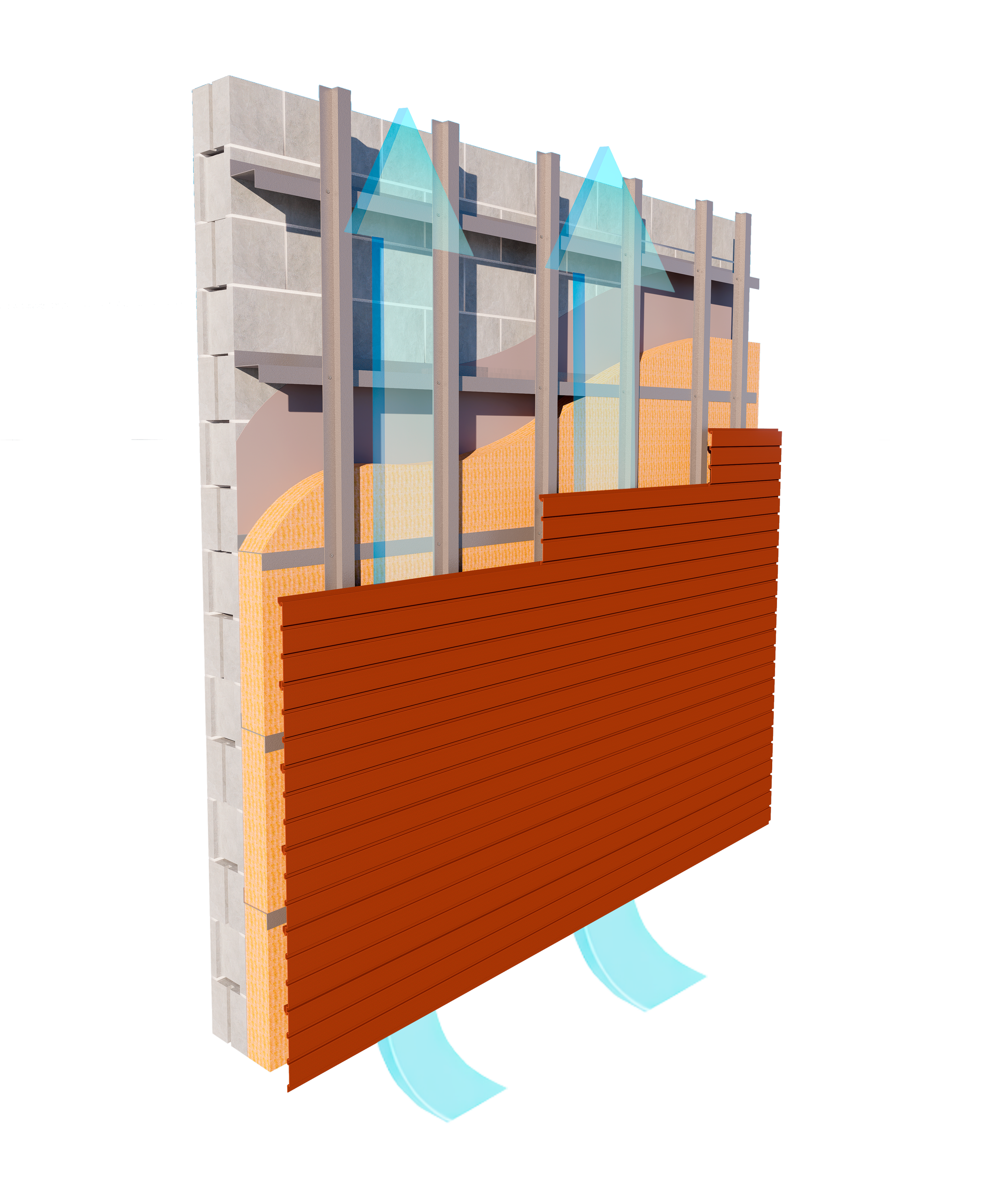
A ventilated aluminum rainscreen can shield the underlying assembly from direct weather exposure while allowing drainage and drying behind the cladding. Those functions support envelope durability, but they should not be confused with insulation value. The project’s thermal resistance is primarily established by insulation, interior and exterior wall components, framing conditions, fasteners and interface details.
This is why an aluminum facade U-value calculation must use the proposed wall construction rather than the nominal R-value of the insulation alone. Repeating clips, girts, slab edges, parapets, shelf angles and transitions can create heat-flow paths that reduce effective performance. The resulting whole-wall U-factor is a more useful specification input than a center-of-cavity value that excludes these conditions.
aPlank panel and plank systems can be coordinated with different insulation depths and attachment layouts, allowing the exterior expression to be developed alongside the wall’s thermal requirements. The appropriate configuration still depends on project-specific loads, substrates, cavity dimensions and energy modeling.

Coordinate the Facade with the Energy Model
Discuss insulation depth, attachment geometry and project-specific thermal requirements with the aPlank facade team before the subframe layout is finalized.
Connect with our team →Thermal Bridging Is Now a Primary Design Variable
Thermal bridges occur where conductive materials bypass or interrupt the insulation layer. In facade assemblies, they may be created by metal clips, continuous girts, structural framing, slab edges, window perimeters, parapets or other penetrations.
These conditions are not interchangeable. Repeating point connections may affect clear-field wall performance, while floor edges and parapets introduce linear losses that can become significant across a large elevation. ASHRAE identifies floor edges, balconies, columns, beams, parapets and roof-to-wall interfaces among the conditions that may function as linear thermal bridges.
Addressing thermal bridging in facades requires more than selecting thermally broken subframing. The strategy should begin before the subframe layout is finalized, with the design team considering:
- The conductivity and geometry of the attachment.
- The percentage of insulation interrupted.
- Vertical and horizontal rail continuity.
- Clip spacing required for structural loads.
- Window, base, corner and parapet transitions.
- Whether thermal effects are included in the energy model.
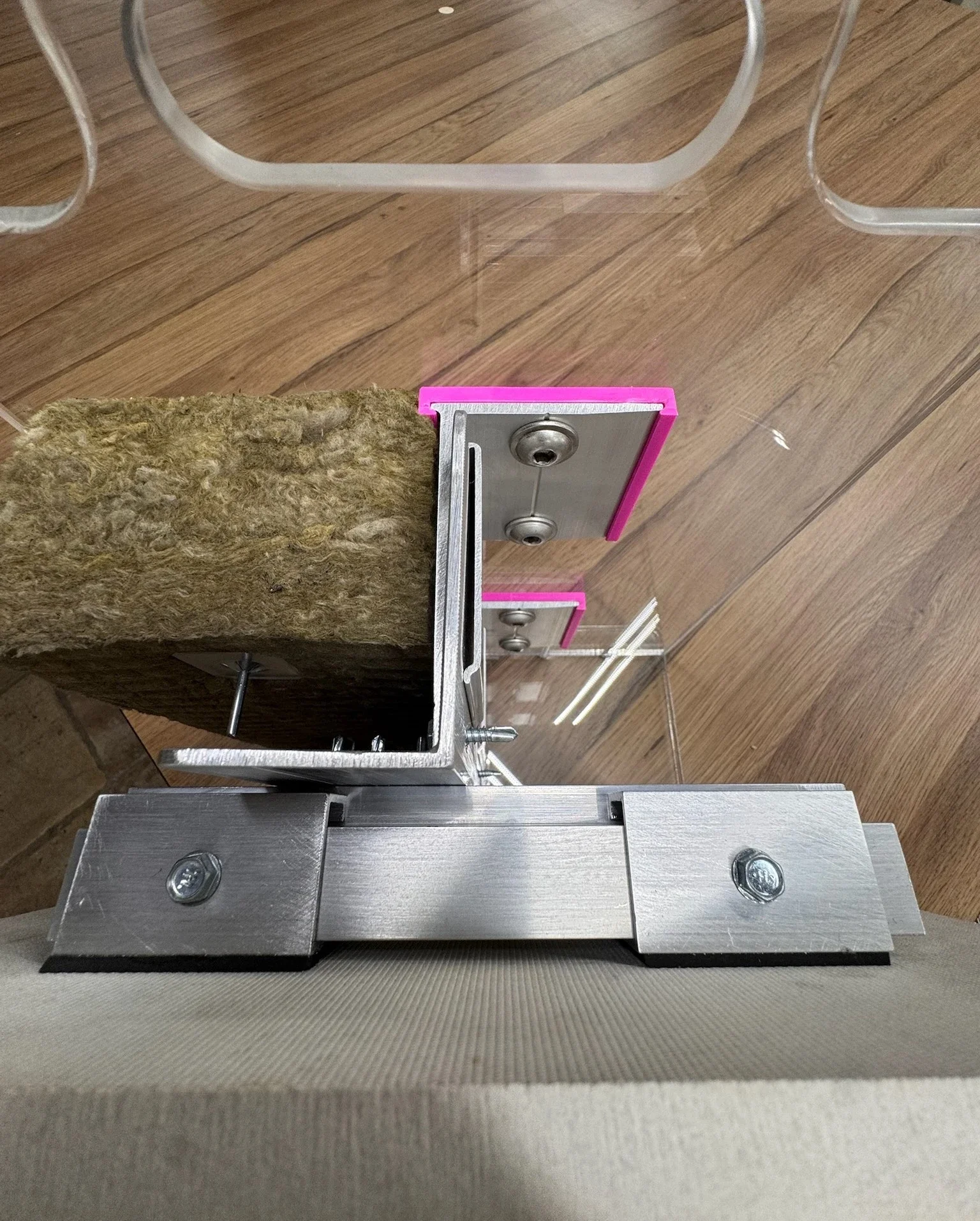
Thermally broken subframing reduces direct conductive paths by incorporating lower-conductivity separation within the attachment assembly. However, “thermally broken” should not be treated as a generic label. The team should request assembly-specific thermal information and confirm that the evaluated geometry reflects the project’s insulation thickness, clip spacing and rail arrangement.
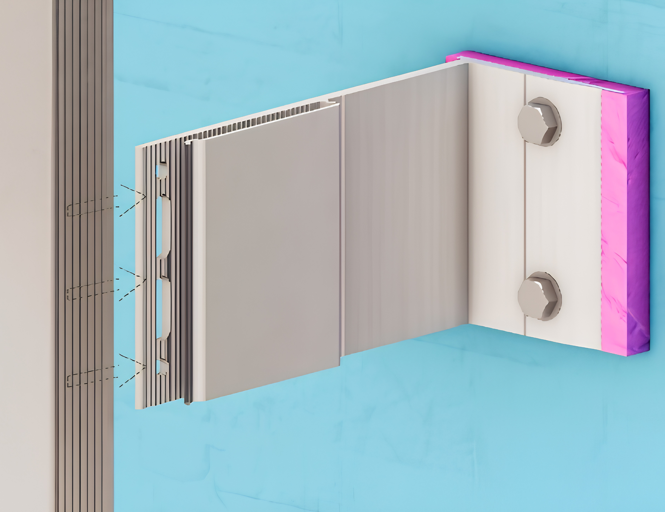
The aFrame thermally broken subframe is designed to support adjustable facade installation while maintaining space for exterior insulation. It can be coordinated with aPlank extruded panels and battens or with other compatible rainscreen materials, allowing the subframe decision to be evaluated as part of both structural and thermal design.

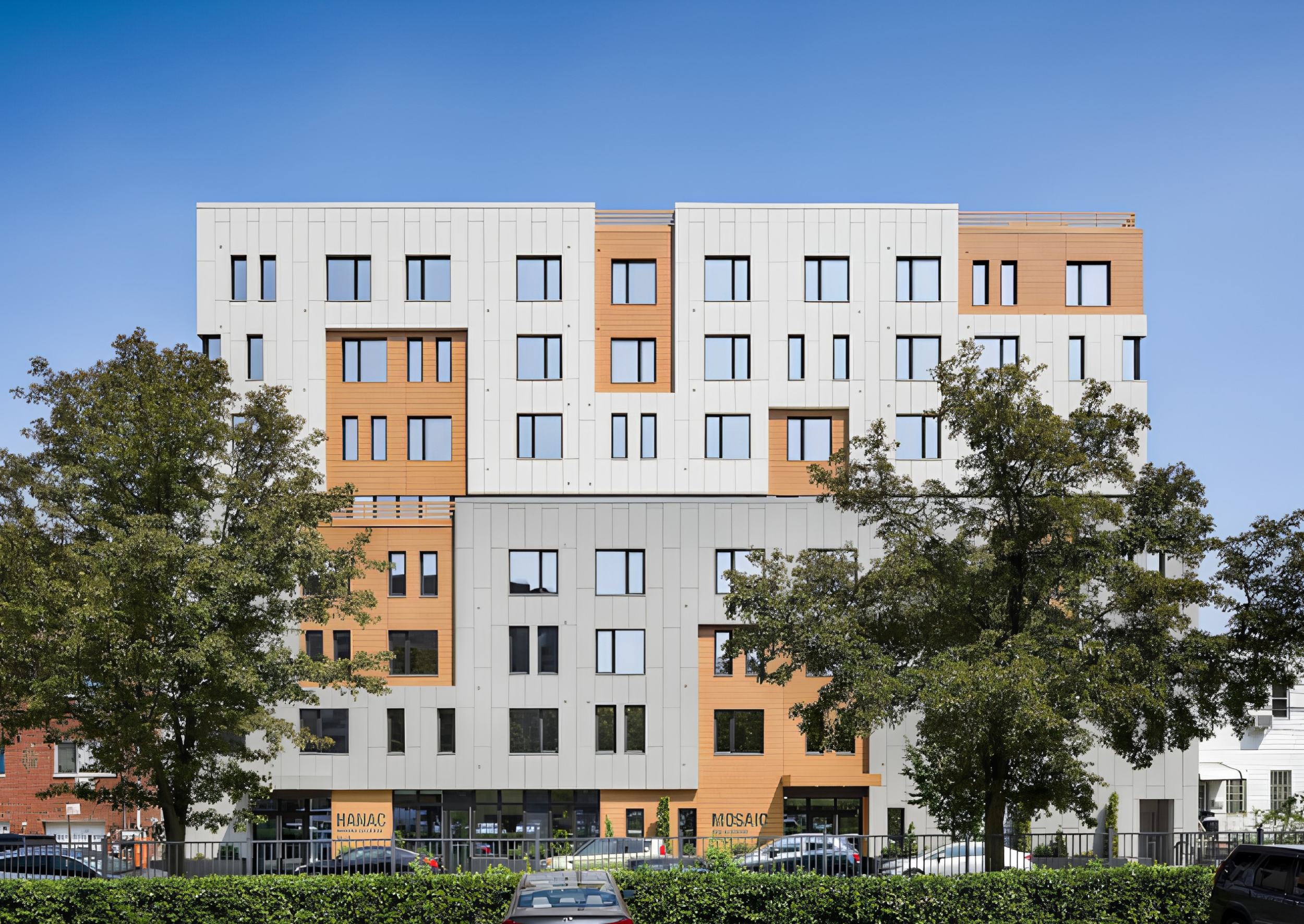
Aluminum rainscreen facade panels in contrasting white and wood-look finishes, a mid-rise commercial installation demonstrating whole-wall cladding coordination.
Translate U-Values Into Buildable Details
Energy models typically represent assemblies through U-factors, which describe heat transmission through the complete construction. R-values describe resistance to heat flow, but adding the nominal R-values of individual products does not automatically represent the wall’s installed performance. This distinction between facade R-values and U-factors becomes especially important when aluminum subframing is introduced.
For facade professionals, the critical step is translating the modeled assembly into details that can be fabricated and installed without breaking thermal continuity. A wall may perform well in a typical-area calculation but lose effectiveness at transitions that were simplified or omitted.
Early coordination should establish:
| Coordination Item | What Must Align |
|---|---|
| Energy Model | The modeled wall construction and assumed thermal properties. |
| Subframing | Clip type, spacing, rail orientation and attachment geometry. |
| Insulation | Thickness, continuity and treatment at transitions. |
| Interfaces | Windows, slab edges, parapets, bases and penetrations. |
| Procurement | Documentation required to evaluate substitutions. |
This creates a natural connection between energy analysis, shop drawings and field review. When a different clip, rail, fastener pattern or insulation thickness is proposed, the change should be evaluated for more than structural adequacy. It may also alter the thermal assumptions behind the approved assembly.
Detailed guidance on aluminum facade U-value thermal performance belongs in project-specific calculations and the dedicated technical spoke. At the Pillar level, the key principle is that the thermal model, facade specification and final attachment layout must describe the same system.
A specified insulation value is only meaningful when the energy model, facade details and installed attachment layout describe the same wall assembly.
Connect Operational and Embodied Carbon Decisions
Improving the enclosure can reduce heating and cooling demand, contributing to lower operational carbon over the building’s service life. Yet a complete sustainability assessment must also consider the emissions associated with producing, finishing, transporting, installing and eventually recovering facade materials.
That distinction is central to current green-building frameworks. LEED v5 identifies decarbonization, including operational and embodied emissions, as one of its principal impact areas. It also introduces requirements and credits focused on quantifying and reducing embodied carbon in major structural, enclosure and hardscape materials.
An embodied carbon aluminum cladding assessment should use product-specific or appropriately representative environmental data rather than general assumptions about aluminum. Recycled content, electricity sources, extrusion efficiency, coating processes, material quantity, service life and end-of-life recovery can all affect the result.
Environmental Product Declarations can support this analysis by reporting standardized life-cycle information. They do not automatically establish that one product is sustainable or guarantee a LEED outcome; they provide data that project teams can use within a defined comparison and reporting method.
For aPlank, the relevant specification conversation extends from profile efficiency and long service life to finish durability, recycled-content information and available product documentation. The existing article on low-carbon aluminum facade systems examines embodied carbon, EPDs and circularity in greater depth. Selecting a profile should balance material use with structural performance, installation requirements and the facade’s intended lifespan rather than pursuing minimum weight as an isolated objective.
Use Certification Frameworks as Documentation Guides
Facade products do not independently certify a building under LEED, WELL or a net-zero program. They may, however, support project strategies when their performance and material information align with the rating system’s requirements.
For aluminum facades in LEED projects, the certification strategy may involve several separate considerations:
Operational Strategy
- Whole-building energy modeling
- Thermal-envelope continuity
- Reduced thermal bridging
Documentation Strategy
- Environmental product disclosure
- Embodied-carbon assessment and responsible sourcing
- Heat-island considerations and construction waste
- Durability and end-of-life planning
Facade design for daylight, thermal comfort and material transparency in WELL projects is part of a broader occupant-health strategy. Facade-related decisions can also influence glare, exterior views, and the ability of the enclosure to manage moisture and outdoor contaminants. Recent WELL v2 updates continue to address daylight-calculation methods and performance-verification requirements.
These contributions depend on the complete building design. They should be documented as part of a coordinated certification strategy rather than attributed to the cladding material alone.
Similarly, facade design for net-zero projects depends on reducing demand before balancing remaining consumption through efficient systems and clean energy. A high-performing enclosure can support that objective, but no cladding system can make a building net-zero without whole-building analysis.
Address Solar Exposure and Heat-Island Objectives Carefully
Color and surface properties affect how an exterior material interacts with solar radiation. On roofs and certain horizontal surfaces, rating systems and codes may establish specific solar-reflectance or thermal-emittance criteria. Vertical facades operate differently and should not be assigned the same assumptions without confirming the applicable program and climate context.
An aluminum rainscreen urban heat island strategy may consider lighter or more reflective finishes, shading geometry, ventilated cavities and reduced heat transfer toward the backup wall. The appropriate response depends on orientation, surrounding surfaces, climate, glare risk and architectural intent. The existing article on reflective aluminum rainscreen systems and urban heat develops this topic in greater detail.
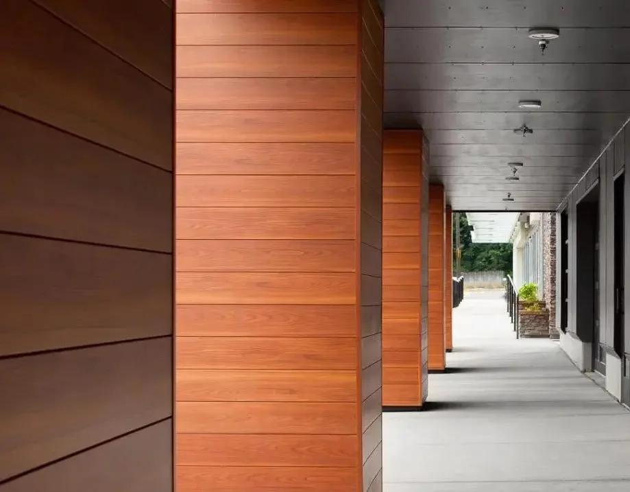
Because aPlank offers solid colors, wood-look finishes and custom finish options, solar-performance criteria can be introduced during finish selection rather than after the facade palette has been approved. When reflectance values are required, the team should request data for the specific coating and color instead of relying on visual appearance.
Specify for Verifiable Whole-Wall Performance
An energy-efficient facade specification should define the information needed to connect design intent with installed performance. At minimum, the project team should coordinate:
- Assembly U-factor or thermal-modeling requirements.
- Continuous-insulation thickness and location.
- Allowable subframe and attachment configuration.
- Treatment of linear and point thermal bridges.
- Air- and water-control continuity at transitions.
- Product-specific environmental documentation.
- Finish data where solar properties are relevant.
- Review procedures for substitutions and field changes.
This approach keeps energy, structural, moisture and carbon decisions within the same coordination process. It also gives contractors and manufacturers clearer criteria for evaluating alternatives.
aPlank supports this process through extruded aluminum panels, planks and battens that can be integrated with the aFrame thermally broken subframe, along with technical details and project-specific system coordination. The objective is not to assign performance claims to one component. It is to help the design team develop an aluminum facade assembly whose geometry, documentation and installed configuration support the project’s whole-wall targets.
Energy-Efficient Aluminum Facades: Common Questions
Does aluminum cladding determine a wall assembly’s R-value?
No. The wall assembly’s thermal resistance depends primarily on insulation, framing, attachments, air spaces, and interface conditions. Aluminum cladding and its subframing affect whole-wall performance by introducing or limiting conductive paths through the insulation layer.
Why must thermal bridging be included in facade energy modeling?
Metal clips, rails, slab edges, parapets, and window interfaces can bypass insulation and reduce effective thermal performance. Including repeating, point, and linear thermal bridges helps align the energy model with the assembly that will actually be detailed and installed.
Can a thermally broken subframe eliminate thermal bridging?
A thermally broken subframe can reduce conductive heat transfer through facade attachments, but it does not eliminate every thermal bridge in the enclosure. Project teams must also coordinate slab edges, windows, parapets, fasteners, and other interfaces.
How can an aluminum facade support LEED or net-zero objectives?
An aluminum facade can support project-level objectives through coordinated whole-wall performance, durable finishes, material documentation, embodied-carbon data, and appropriate solar-control strategies. The facade product does not independently earn certification or make a building net-zero.