Energy Efficiency
Continuous exterior insulation can appear uninterrupted in a wall section while still being compromised by the system supporting the cladding. Each bracket, fastener, rail, shelf angle, and transition that crosses or displaces the insulation creates a potential path for conductive heat flow.
For facade teams, the relevant question is not simply whether a subframe is described as thermally broken. It is whether the proposed attachment geometry, spacing, rail configuration, and interface conditions reduce heat transfer in the assembly that will actually be built. This connects subframing decisions to the broader performance of energy-efficient aluminum facade systems, where insulation continuity and attachment design must support the same whole-wall assumptions used in the energy model.
Why Subframing Changes Facade Thermal Performance
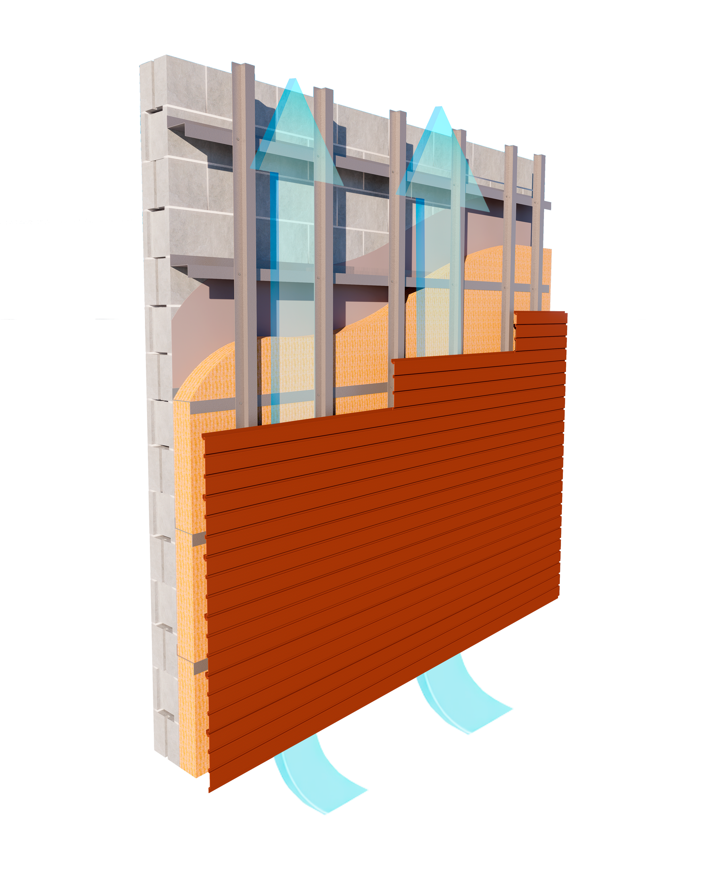
In a ventilated rainscreen, the insulation and air barrier generally sit behind the cladding and its support system. The cladding is not the primary insulating layer, but its attachments can bypass that layer and reduce effective wall performance.
Continuous exterior insulation limits heat flow through structural framing, but the supports required to carry the facade still penetrate or interrupt the insulation. A continuous metal girt creates a different conductive path than an intermittent clip-and-rail system. Even among thermally broken systems, performance varies with bracket geometry, projection, material, fastener count, and contact area.
For this reason, the nominal R-value of the insulation does not represent the installed wall by itself. The U.S. Department of Energy describes continuous exterior insulation as a means of reducing thermal losses through framing-related bridges. The same principle makes the cladding attachment layout part of whole-wall evaluation rather than a secondary installation decision.
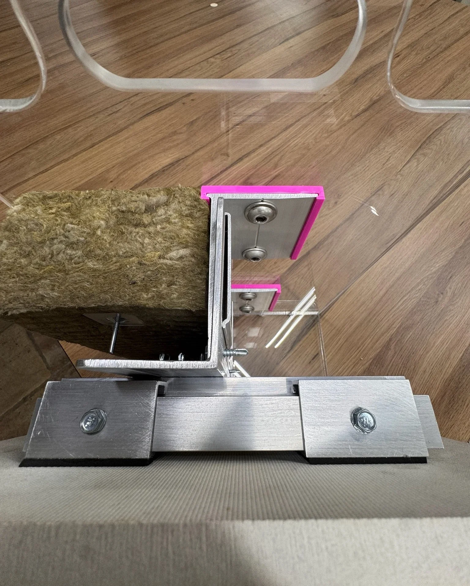
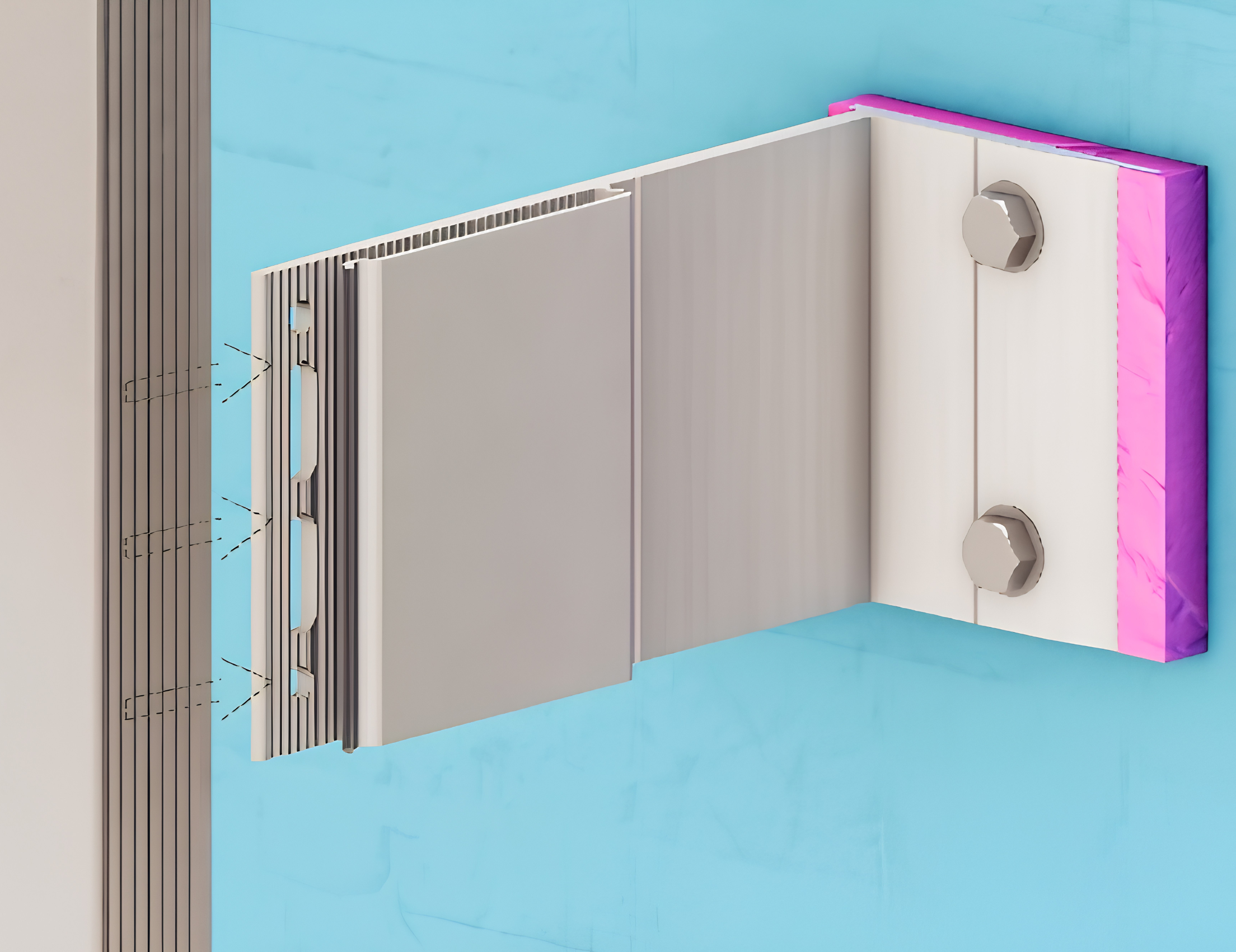
The aFrame subframing system uses an adjustable bracket-and-rail configuration designed to support exterior insulation while reducing direct conductive paths through rainscreen attachments. Its thermal contribution still depends on bracket layout, rail configuration, insulation fit, and the project-specific wall assembly.
Thermally Broken Clip and Rail
- Lower-conductivity separation within the attachment path
- Intermittent connection points through exterior insulation
- Spacing engineered for project loads and thermal goals
Continuous Metal Support
- More conductive material crossing or contacting insulation
- Repeating path can reduce effective wall resistance
- Thermal impact depends on exact geometry and continuity

Explore the aFrame System
See how the thermally broken, adjustable aFrame system supports continuous exterior insulation, varied cavity depths, and a wide range of rainscreen cladding assemblies.
View the aFrame system →What Makes a Thermally Broken Subframe Effective?
Attachment Geometry and Contact Area
The amount of conductive material crossing the insulation affects heat transfer. Bracket cross-section, depth, metal-to-metal contact, and fastener placement all influence the path. Two systems using similar isolation materials may therefore deliver different results.
Clip Spacing and Structural Loads
Wider clip spacing can reduce the number of penetrations, but spacing must still satisfy wind pressure, cladding weight, substrate capacity, and allowable deflection. The objective is to balance attachment efficiency with load transfer, including denser layouts where perimeter pressures or panel geometry require them. aFrame brackets are available in standard and XL configurations, allowing the support system to respond to different cladding and wind-load demands. Higher-load conditions may still affect bracket size, spacing, and the amount of conductive material in the assembly, which is why the evaluated thermal configuration should match the engineered facade layout.
Rail Direction and Insulation Continuity
Vertical and horizontal rails provide alignment and distribute loads, but their orientation and continuity influence the repeating thermal path. Performance can also be reduced when insulation is compressed, heavily notched, or displaced around attachments. Insulation should be cut and tightly butted around the aFrame brackets, then secured with appropriate fasteners so it maintains continuity without obstructing the ventilated cavity. Bracket projection and cavity depth should accommodate the specified insulation while maintaining drainage and ventilation space.
The attachment layout must also allow the subframe to accommodate movement. In the aFrame configuration, one fixed connection establishes the profile location while subsequent slotted connections permit expansion and dynamic movement. These structural details should be coordinated without introducing unnecessary attachment density or compromising insulation continuity.

The aFrame thermally broken subframing system coordinates cladding support, cavity depth, and thermal separation within an aPlank rainscreen facade assembly.
“A thermal break is only as effective as the bracket, rail, fastener, insulation, and transition details surrounding it.”
— aPlank Technical EditorialEvaluate the Configuration, Not the Label
“Thermally broken” should be treated as a performance characteristic supported by assembly-specific information, not as a specification checkbox. The project team should verify that thermal data reflects the proposed insulation, bracket spacing, fasteners, rail orientation, and backup wall.
ASHRAE Standard 90.1 building-envelope guidance distinguishes conditions that cannot all be treated through one simplified value. Repeating supports affect the clear-field wall, while floor edges, parapets, balconies, roof-to-wall interfaces, and discrete penetrations introduce linear or point effects.
Confirm the modeled assembly
Match insulation, substrate, bracket type, clip spacing, rail direction, and fasteners to the configuration being evaluated.
Coordinate structural zones
Identify corners, panel ends, openings, and higher-pressure areas where attachment density may change.
Review facade transitions
Track continuity at bases, windows, parapets, shelf angles, roof edges, and structural penetrations.
Protect assumptions through submittals
Recheck thermal implications when clips, rails, fasteners, insulation, or substrates are substituted.
Coordinate the Typical Wall and Its Transitions
Thermal continuity is often most difficult to maintain where the facade changes direction or connects to another assembly. Window perimeters, bases, corners, parapets, slab edges, canopies, and structural penetrations may require denser attachments, blocking, or different bracket arrangements.
This review should continue through shop drawings and substitutions. Changing clip type, spacing, rail profile, fastener pattern, or insulation thickness may alter both structural behavior and the thermal assumptions associated with the approved wall.
Positioning aFrame Within the Thermal Strategy
The aFrame thermally broken subframing system provides an adjustable bracket-and-rail platform designed to support exterior insulation and ventilated rainscreen assemblies. Its configuration can respond to insulation depth, design pressures, substrate conditions, and required cavity dimensions.
With V4, V6, V8, and V10 bracket options, aFrame can accommodate system depths from approximately 4 to 12 inches, with field adjustment for line and level. This range allows the attachment plane to be coordinated around different insulation depths and facade cavities rather than applying one fixed projection across every wall condition.
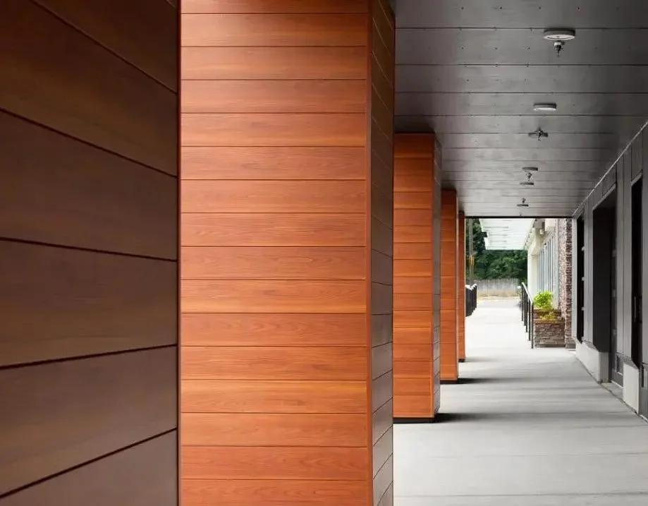
It can support aPlank extruded aluminum cladding panels, battens, and other compatible facade materials. Its value is not based on claiming that every thermal bridge disappears. Instead, aFrame gives teams an engineered way to reduce direct conductive paths while coordinating cladding loads, installation tolerances, movement, and enclosure requirements.
Thermal Bridging and Facade Subframing FAQs
Does thermally broken subframing eliminate all facade thermal bridges?
No. It reduces conductive heat flow through recurring cladding attachments, but linear and point thermal bridges can remain at slab edges, parapets, windows, shelf angles, fasteners, and other transitions. Those conditions still require project-specific coordination and thermal analysis.
What information should be reviewed when comparing thermally broken subframes?
Review the complete proposed configuration, including bracket geometry, thermal-break material, clip spacing, fastener count, rail orientation, insulation thickness, substrate, and design loads. Product labels or isolated material conductivity values are not enough to represent whole-wall performance.
Can clip spacing be increased only to improve thermal performance?
No. Wider spacing may reduce the number of conductive penetrations, but the layout must still satisfy wind pressure, cladding weight, substrate capacity, deflection limits, and perimeter-zone requirements. Structural and thermal criteria should be resolved together.
How does aFrame support continuous exterior insulation?
The adjustable aFrame bracket-and-rail platform can be coordinated around insulation depth, cavity requirements, substrate conditions, and cladding loads. Its thermally broken configuration is intended to reduce direct conductive paths while maintaining a workable support plane for ventilated facade systems.